

House Structure Basics
Note: definitions for the underlined words in this chapter are found in the Glossary of Terms
Regardless of what type renovation project you may be planning, a basic understanding of your home’s structure and mapping of its systems will help you better assess project complexity, renovation requirements, costs, and time involvement. As well as whether or not your renovation plans are something you can accomplish yourself, or if you need to seek the skills of a professional.
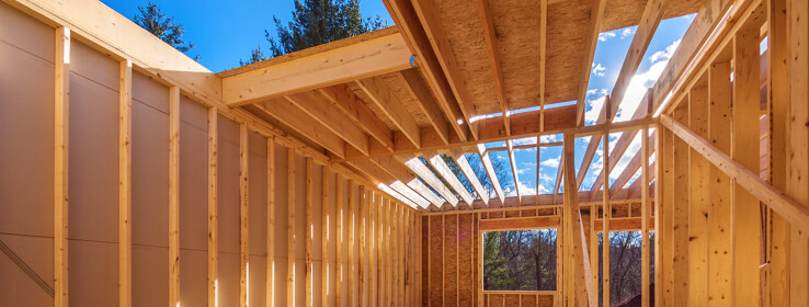
Styles of Framing
There are two basic styles of house framing:
- Balloon
- Platform
Balloon framing has studs that run uninterrupted from the roof to a sill plate on the foundation. Studs in platform framing, on the other hand, are attached to floor-level bottom plates (horizontally running framing members along the floor), and ceiling level top plates.
Most homes built after 1930 use the platform style of framing. One reason is that this type framing is easy to alter during home renovations. That is because the support structure for each story begins at the floor level of that story, while balloon framing uses wall studs that extend from the foundation walls of the structure to the roof.
The type framing your house has will determine complexity of renovation projects that alter the structure’s frame. Framing type also determines what type temporary structural supports will be required during the construction period.
Determine the structural framing type of your home by either referring to the original blue prints of your home, or consulting with a building contractor or your local building inspector.
Aspects of Framing
There are four aspects of home framing that work together to form a solid structure:
- The roof
- The walls
- The floors and ceiling
- The foundation
Roof framing involves the construction rafters, or the purchase of prefabricated frames. Rafters are most often made using 2X6 or larger lumber spaced 16 to 24-inches apart; spanning from the exterior walls to the ridge board or beam, at the peak of the roof.
Ceiling joists usually link the ends of opposing rafters, creating a structural triangle. Rafter ties or collar ties are sometimes used for additional support.
Trusses are usually made using 2X2 lumber joined with metal plates or fasteners. Standard trusses have bottom and top cords with interconnecting webs for stability. Trusses can be found in many homes built after 1950. The down side of prefabricated roof frames such as these is that they cannot be cut or altered in any way.
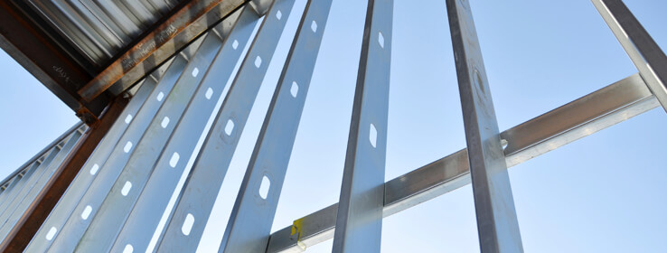
Wall framing uses studs; vertical framing members spaced at regular intervals that make up the interior and exterior walls of the home’s structure. While commercial structures most often use metal studs, residential dwellings most often use wood; either 2X4 or 2X6s.
Floor and Ceiling Framing consists of joints; the ends of which rest on support beams, foundations, or load-bearing walls. Joists always run perpendicular to their supports, and carry the structural load of floors and ceilings. Most joists are made using 2X10 or larger lumber.
Ceiling joists generally use smaller lumber, 2X4 or larger, since they support only a ceiling finish and sometimes small storage space. Blocking or X-bridging is usually installed between joists for added support.
Floor joists used in balloon framing are nailed to the sides of the continuous wall studs. Upper-story joists gain added support from 1X4 ribbons that have been notched into the studs below the fire blocking – nailed between each joist for fire protection.
Foundation wall framing and a girder, or main beam, supports the frame of the house. This is true regardless of whether the house has balloon or platform style framing. In turn, the foundation framing is supported by the earth that surrounds it.
Mapping out House Systems
Mapping out house systems such as plumbing, wiring, and heating is a critical part of home renovation planning. Likewise, understanding aspects of house structure and type of framing used is also important.
While many do-it-yourself homeowners feel comfortable handling less complicated renovation projects themselves, larger, more complicated projects often require at least some input from a professional building contractor.
Aside from wood framework, home structure also involves the following:
- Plumbing
- Wiring
- HVAC system (heating, ventilation, and air conditioning)
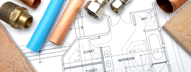
PLUMBING
Plumbing fixtures in most houses are located near the 3 or 4-inch drain-waste-vent (DWV) pipe. Also known as the main stack or soil stack; or auxiliary DWV stack. The DWV extends from the basement floor to the roof, serving as the drain and vent for multiple fixtures.
Typically, plumbing in residential structures involves not just a water supply system; it also involves fixtures and a drain system. It works something like the following:
- Fresh water enters the home through a main supply line. As it does it usually passes through a meter that registers the amount of water flowing into the house.
- After entering the home, the water line branches off; some of the water feeds into a hot water heater. Warmed water from the heater flows through a line that runs parallel to the cold water line, feeding fixtures and appliances within the home.
- Waste water from fixtures and appliances flow into a trap, then into a drainage system that travels downhill through a series of large-diameter drain pipes.
- The drain pipes are attached to a system of vent pipes that allow air into the system through a roof vent. This keeps the drain water flowing properly.
Eventually the drain water reaches a main waste and stack vent that directs the water into an underground sewer line. This carries the water away from the house and into a municipal sewer system or a septic tank.
Supply Pipes
It is the cold and hot water supply pipes that make up the home’s plumbing system. Before 1950 most supply pipes were made from galvanized iron. Homes built after 1950 generally used copper or plastic (CPVC) pipes. Many homeowners use a home renovation as an opportunity to replace old supply pipes with new.
Supply pipes are manufactured to withstand high water pressure. They are usually ½-inch to 1-inch in diameter and are joined with strong, watertight fittings. Valves are used to control the flow of water.
Water supply systems are generally located inside wall cavities, or strapped to the undersides of floor joists.
Drain Pipes
Drain pipes carry water out of the house via a DWV system; drain-waste-vent. This system uses gravity to draw water down vertical pipes and along a sloping path into a municipal sewer system or septic tank.
Although drain pipes found in older homes are generally made from copper or lead, pipes in newer homes are made from plastic or cast iron. Drain pipes are larger than supply pipes; usually 1¼-inches to4-inches in diameter.
The curved section in the DWV is called the trap. The trap holds a supply of standing water. This prevents toxic sewer gases from entering the home. Every time the drain is used, old standing water is replaced with new.
Outdoor air is brought into the house by the vent system in the drain pipes. This lowers pressure in the pipes and helps keep the water flowing freely. Improperly constructed drain systems can create drain malfunctions, interfere with toilet flushing, and allow
sewer gas to back up and enter the home.

WIRING
Wiring is the home’s electrical system. It is made up of many circuits; each of which start from a main service panel, and sometimes a sub-panel. Standard electrical wiring is slim and flexible. Although this makes it difficult to follow the exact route of each circuit, adding new circuits is made easier.
Many types of home renovation projects entail changes to the existing wiring system. Most homeowners prefer to hire a professional electrician or other service provider experienced with wiring systems. But DIY homeowners with an understanding of their home’s electrical system can easily complete many aspects of wiring themselves if local building codes allow; as long as they follow good safety practices.
An electrical system includes the following:
- The service head – also sometimes called a weather head. This anchors the overhead service wires that run into the home. Service wires generally consist of two wires that supply 120-volt current, and one grounded or neutral wire.
- The electric meter box – keeps track of every watt of electrical current consumed. The box is usually attached either directly to the house, or a nearby pole; it is connected either to the service head, or power lines that are buried.
- The breaker box – also called the main service panel or fuse box. This distributes power to individual circuits, each for its own purpose. Circuit breakers are safety features in the breaker box that shut current down in the event of an overload or short circuit.
- Electric boxes – made from plastic or metal; they enclose wire connections and are a requirement of the National electrical code (NEC).
- Outlets – also called receptacles. They provide plug-in access to power; two prong 125-volt; three prong 15-amp.
- Power Switches – control the flow of current and turn individual power sources on or off.
Any time a home renovation project includes electrical wiring, extreme caution should be used. It is noteworthy to mention that unless the utility company shuts them off, the wires that connect the service head, electric meter box and breaker box are always live. Never attempt to repair or alter any of these devices. If there is a problem with any of them, promptly contact your utility company.

HVAC
HVAC is the home’s heating and cooling system. In a forced-air heating system, the furnace feeds a main supply duct. This branches off to other ducts that lead to the various rooms of the house. Other ducts circulate cold air back to the furnace. Ducts that service the upper floors of a house usually rise straight up through the cavities of wall studs.
Some homes use a passive heating system, one that does not employ the use of a fan. A hydrolic system, for instance, uses hot water or steam and a network of pipes to circulate heated water from a boiler to heaters located throughout the house; whether baseboard, convectors, or radiators.
When renovation projects alter the plumbing, wiring, or HVAC system in any way, it is important to accurately map out each of these systems when still in the planning stage. This can be a complex process, as investigation of the course of pipes, wires, cables, and ducts can be difficult to chart. Yet, knowing exactly what is behind the surface of walls, floors, and ceilings – before work begins – is essential.
Key points to remember before beginning any project that will alter your house’s plumbing, electrical wiring, HVAC system, or structure in any way:
- Accurately assess the structure and system of your house, and draw up a detailed diagram.
- Draw up a detailed plan of your home renovation project.
- Show your plans to a local building inspector for approval.
- Obtain all necessary permits that may be required before work begins.
WALLS – INTERIOR AND EXTERIOR
Walls of residential structures consist of wood frames covered by such materials as lath, plaster, drywall, paneling, siding, and masonry.
Interior walls
Interior walls begin with a horizontal sole plate that has been nailed to the subfloor. The plate is used to support vertical studs, nailed to a horizontally running top plate. Locations on the wall where there will be an opening usually have double studs topped by a header; usually two 2X4s or 2X6s. This is to increase rigidity and add support.
Some wall frames may also include fire blocking; usually at 4-foot levels, placed horizontally between studs.
Exterior Walls
Exterior Walls are usually constructed with a sill plate and box sill that rests on top of the foundation. A sole plate with 2X4 or 2X6 vertical studs spaced 16 or 24-inches apart. A top plate is made using 2X4s or 2X6s, resting either the rafters or framing for the second story.
Insulation to conserve heat and wood or composition board for strength is then topped with a layer of air wrap. This might consist of asphalt-saturated building paper or plastic that acts as a seal. Outside framing (wood, shingles, siding, masonry, or another material) protects against the elements and adds visual appeal to the structure.
WALLS – LOAD AND NON-LOAD BEARING
In addition to the differences between interior and exterior walls and their makeup, another important factor in regards to walls is whether or not they are load bearing or non-load bearing.
As the name implies, load-bearing walls carry the structural weight of your home. Load- bearing walls in platform-frame homes will have double top plates. That is, two layers of framing lumber. Note: all exterior walls are load bearing; interior walls that are aligned above support beams are also lead bearing.
Non-load-bearing walls support only themselves; they are interior partition walls. They have a single top plate. While non-load-bearing walls might run perpendicular to floor and ceiling joists, they will not be aligned above support beams. Note: all walls that run parallel to joists are non-load bearing.
While non-load-bearing walls can be altered or even removed completely without weakening the home’s structure, alterations that can be made to load-bearing walls are limited. And may require the placement of temporary supports for certain types of remodeling projects.
MAKING TEMPORARY SUPPORTS
When alterations are made to a load-bearing wall that will remove more than one stud, it is necessary to make temporary supports before beginning the project. Type of support required differs depending upon the type framing of the house – platform or balloon, as well as on the extent of the alteration, and how long it will take to complete the job.
For instance, say your house has a platform frame. A remodeling job that requires a large opening in a load-bearing wall will require two temporary ceiling joist supports; one on either side of the wall. Use either the hydraulic jack method or make a temporary stud wall. The temporary stud wall method should be used if the supports will have to remain in place for more than a day.
BALLOON FRAMING
Many homes built before 1930 used balloon framing. Balloon framed houses require temporary support headers called whalers when making alterations that affect more than one stud in a load-bearing wall.
For instance, say you plan on making an opening for an archway or window on a ground floor exterior (load bearing) wall. The whaler would be anchored to the wall studs above the planned rough opening, and extend at least 20-inches beyond each side of the opening. It would be supported with wall studs and bracing that would run adjacent to the rough opening.
To accomplish this, you would follow the directions below:
- Mark the area for the rough opening; remove wall surfaces around the rough opening, from floor to ceiling.
- Using a 2X8 long enough to extend beyond the planned opening; center the whaler against the wall studs, flush with the ceiling. Tack in place using 2-inch wallboard (flattop) screws.
- Cut two lengths of 2X4 to fit snuggly between the bottom of the whaler and the floor.
- Slide the 2X4s into position at the ends of the whaler; carefully tap until the 2X4 and whaler surfaces are flush and the 2X4s vertically straight. Attach using nailing plates and 3-inch nails.
- Use a drill with a 3/16-inch bit to drill two holes through the whaler and into each stud it spans; secure the whaler using 3/8 X 4-inch lag screws with a washer.
- Using a hammer, carefully tap tapered shims into place between the bottom of each temporary 2X4 support and the floor.
To make changes to an interior load-bearing wall on a balloon framed house, or one located on an upper floor, confer with a professional contractor. Have the contractor assess the wall before suggesting the best placement and type off temporary support for your project needs.
PLATFORM FRAMING
Most homes built after 1930 were constructed with platform framing. Temporary support systems for platform framed houses should hold up the ceiling joists. This is because the ceiling platform, and not wall studs, carries the upstairs load. Supports can be made using either a hydraulic jack or temporary stud wall methods.
Temporary Hydraulic Jack Supports
If the ceiling joists run perpendicular, you would make a temporary hydraulic jack support the following way:
- Cut three 2X4s that are 4-feet longer than the planned rough opening on the wall.
- Make a top plate by nailing two of the 2X4s together using 3-inch nails; use the remaining 2X4 as the temporary bottom plate.
- Place the bottom plate on the floor about 3 feet from the wall to allow room to work; center it at the planned rough opening.
- Put one hydraulic jack 2-feet from eachend of the bottom plate. If the opening will be more than 7 or 8-feet wide, use three jacks. One at each end, the other centered in the middle.
- Build a post for each jack by nailing together two 2X4s; make each post 3 to 4- inches shorter than the distance between the top of the jack and the ceiling.
- Use 3-inch counter sunk lag screws to attach the posts to the temporary top plate; position end posts 2-feet in from the ends of the top plate.
- Cover the surface of the top plate with clean toweling, rugs, or other material to prevent damage to the ceiling.
- Lift the structure into place, positioning the posts onto the hydraulic jacks. Adjust the structure to ensure it is plumb.
- Carefully raise the hydraulic jacks until the top plate makes contact with the ceiling and just begins to lift it. Do not lift too far or you could cause damage to the floor or ceiling.
In the event ceiling joists run parallel to the project wall, alter the above directions to include the following steps:
- Using two 2X4s nailed together, make two 4-feet long cross braces.
- Attach the cross braces to the temporary top plate, centering each brace 1-foot in from the ends of the top plate.
- Make sure that the bottom plate of the temporary support is directly over a floor joist.
- In step 5, instead of making each post 3 or 4-inches shorter than the distance between the top of the jack and the ceiling, increase the distance to 8-inches.
- In step 7, instead of covering the top plate with material to protect the ceiling, cover the surface of the braces.
- In step 9 carefully raise the jacks until the cross braces makes contact with the ceiling and just begins to lift it. Do no tlift too far or you could cause damage to the floor or ceiling.
Temporary Stud Wall Supports
As mentioned earlier, if temporary support needs to be left in place for longer than one day and ceiling joists run perpendicular to the project, opt for a temporary stud wall instead of hydraulic jack supports.
Do the following:
- Using 2X4s construct a stud wall thatis 4-feet wider than the planned wall opening, and roughly 1¾-inch shorter than the distance from the floor to the ceiling. Space studs 16 to 17-inches on center.
- Position the stud wall about 3-feet from the project wall to allow room to work; be sure it is centered at the planned rough opening.
- Slide a 2X4 the same length as the top of the temporary stud wall in between the temporary wall and the ceiling; be sure the wall is plumb.
- Carefully drive wood shims between the top plate and the 2X4 at 12-inch intervals.